L&t Timer Switch Wiring Diagram
The mains failure delay timer expires, the load is switched off from Terminal 94 and 95 work as the starting button and terminal 95 and 96 work as stoping or reset button.
Wiring order for A Traveller Remote Control Awesome

Same potential must be applied to a1 and b1, or a3 and b3.

L&t timer switch wiring diagram. Note that one one of the contactor acts as a switch for the start button. Here is a picture gallery about leviton timer switch wiring diagram complete with the description of the image please find the image you need. Functions with signal start without signal start wiring diagram type 86.00 86
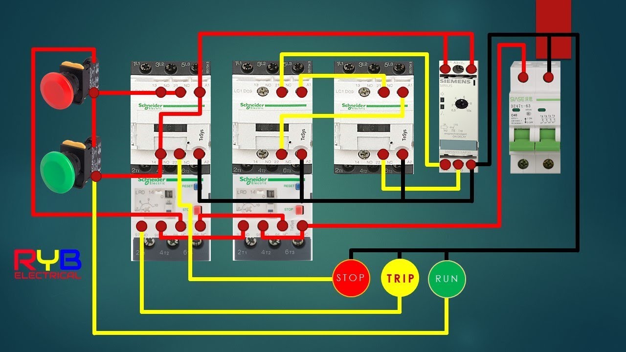
In the above star delta starter control circuit wiring diagram with timer and normally close push buttonnormally open push button switch. Analog time switch fm/1 quartz wiring diagram. In a starter, closed contact (after receiving input) is used in the star side circuit and normally open contact is used in the delta side starter circuit.
Either of the two start buttons will close the contactor, either of the stop buttons will open the contactor. Price list for mk1 0.25. Start fiber optic transceiver class 9005 type ft fiber optic push button, selector switch, limit switch, etc.
• the activation of loads parallel to the start input is not permissible when using ac control voltage (see diagram below). 67ddt0 (black) online at low price in india on amazon.in. A 8 pin timer are used.
Voltage (refer wiring diagram fig.1). The fm/1 series of time switches are designed for control of nects and make connections in accordance with the wiring diagram shown diagram). 1.5 schematic circuit diagram for automatic transfer switch 1.6 recommended cable size 1.7 specifications.
Star delta starter diagram with connection of 3 phase motor and control circuit wiring. In control wiring diagram all magnetic contactors coils are rated 220 vac. The following diagrams show the terminal strips in the control box.
L&t motor starter handbook electrical standard products larsen & toubro limited powai campus, mumbai 400 072 tel: The vänee controls are very easy to install! Wiring diagram book a1 15 b1 b2 16 18 b3 a2 b1 b3 15 supply voltage 16 18 l m h 2 levels b2 l1 f u 1 460 v f u 2 l2 l3 gnd h1 h3 h2 h4 f u.
This wiring diagram shows both switches aligned together with the fixture at the end. Motorised switch cl ncl g q1 q2 ats automatic transfer switch protection aren't shown on the following schemes summary. Power busbar and control wiring are color coded.
(effectively looking the start button closed. The on delay timer diagram is also shown in the diagram. One is power circuit and another one is control circuit.
1 less than a minute. It consists of two normally open contacts. For price list call shopelect:
Buy gic l&t daily weekly programmable electronic 110 240 vac crono timer switch, 50/60 hz, 1 c/o spdt cat. L t r a f l o d e a d e n d f i l l s y s t e m i n s t a l l a t i o n m a n u a l • p a g e 1 1 dead end fill system wiring diagram (single phase, w/o starters) to be used with all systems except model 108 high capacity two motor tandem systems. Identify and locate the pool pump timer s wire terminals using the timer s schematic as a guide.
For understanding let we take siemens to make. We have electrical products for all type of industrial usage. • off delay timers are with aux.
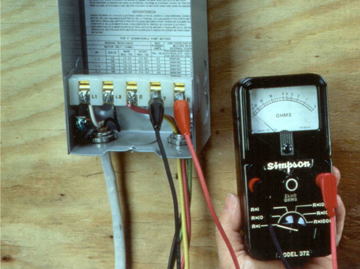
Franklin Electric Submersible Pump Electrical Connection
Orbit Pump Switch Wiring Diagram Image
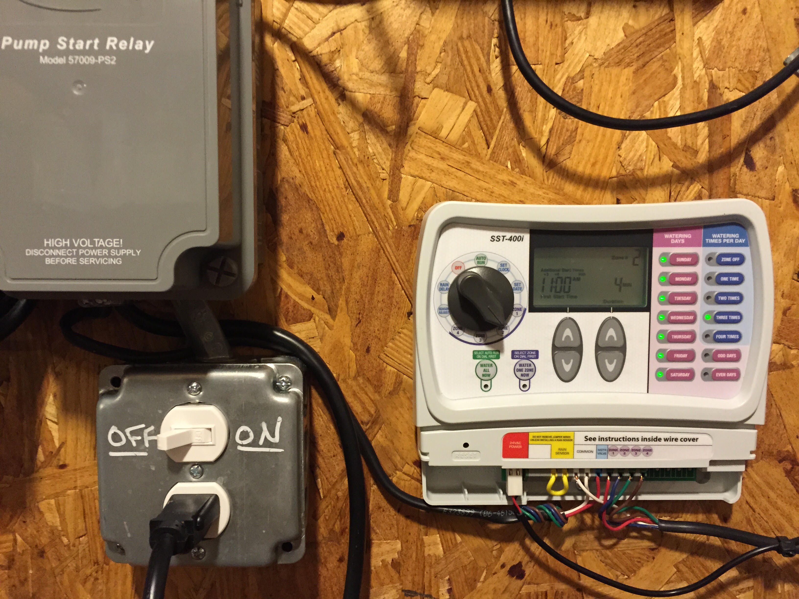
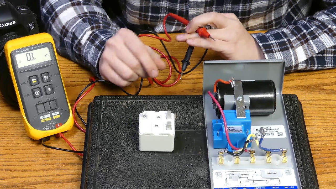
Pump Start Relay Wiring Wiring Diagram Image
Hager 3 Phase Changeover Switch Wiring Diagram Wiring

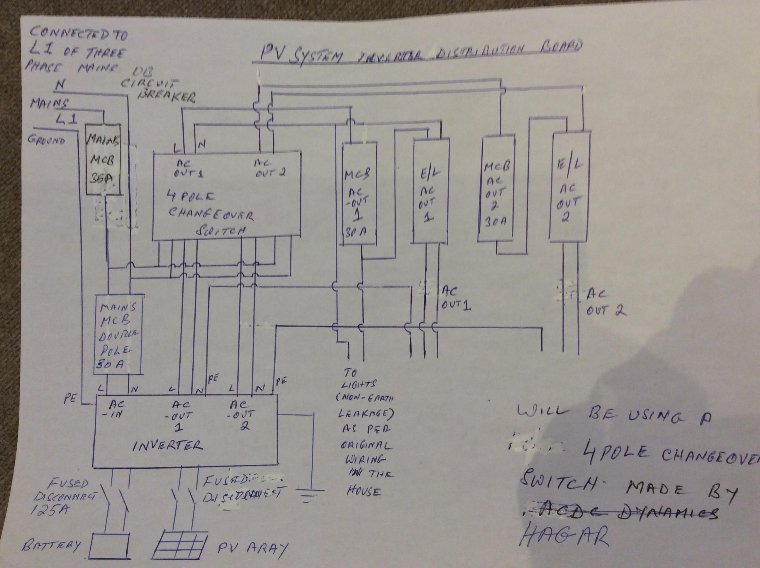
Hager 3 Phase Changeover Switch Wiring Diagram Wiring
Whole House Fan Timer Inspirational Wiring Diagram Image

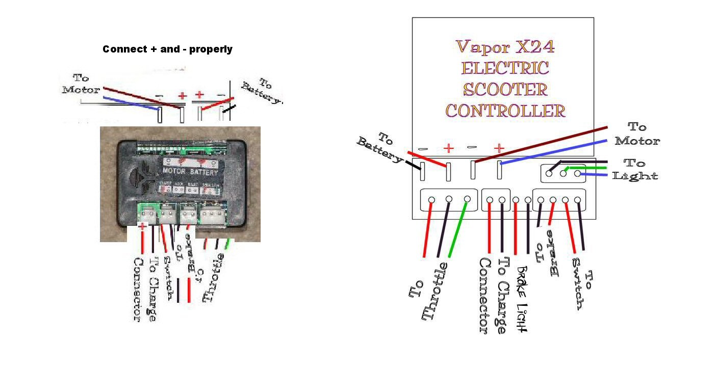
E Bike Controller Schematic Wiring Diagram Image
L&T Starter Wiring Diagram Professional FASD, Electrical


Star Delta Timer Wiring Diagram Datasheet

Timer Connection Diagram YouTube

L&t Star Delta Starter Wiring Diagram Wiring Diagram Wall

L T Gic Analog Timer at Rs 1430 /piece Kalbadevi
Whole House Fan Timer Inspirational Wiring Diagram Image


Analog Timer Connection Diagram Wiring Schematic Diagram

Dol Starter Circuit Wiring Diagram CASSANDRALANDER
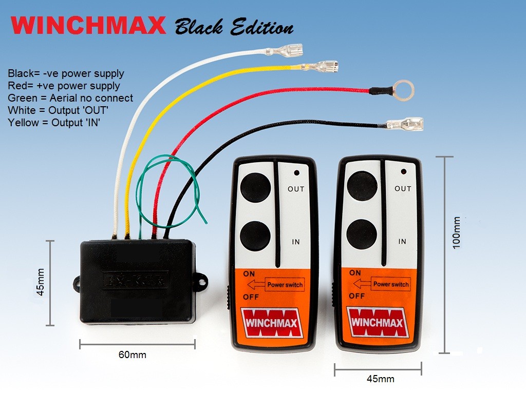
Traveler Remote Winch Control Diagram Wiring Diagram Image
[42+] Gic Star Delta Timer Wiring Diagram
Home Automation Wiring Diagram Pdf Review Home Decor
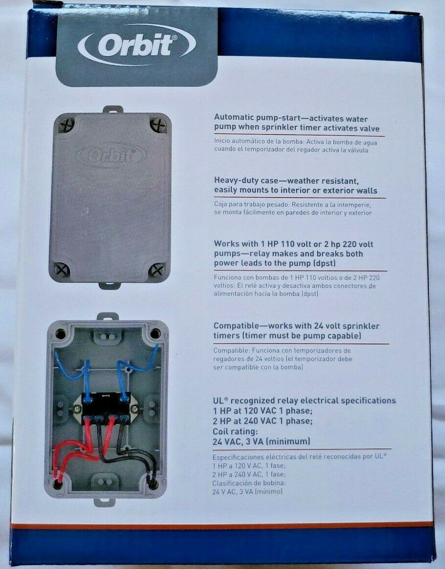
Orbit Pump Switch Wiring Diagram Image