5.1 Prologic Board Circuit Diagram
In australia, the ej205 was available in the sf.ii forester gt from august 1998 and the gc.ii/gm.ii impreza wrx from september 1998. However, applications may support load impedances of 5k ohms and above.

5.1 Prologic Board Circuit Diagram 3000W Stereo Power Amplifier Circuit Audio amplifier
In australia, the ej20k engine powered the subaru gc/gm impreza wrx from november 1996 (for the 1997 'model year' or my97) to 1998.

5.1 prologic board circuit diagram. The center track is 0.15 inch wide and 0.005 inch thick and the pc board first layer thickness is 0.05 inch thick, with an overall board thickness of twice the single layer. For the subaru gc/gm impreza wrx, key features of the ej20k engine included: What is the characteristic impedance?
The latest tweets from nudo【メンズコスメ/メンズメイク】 (@nudo_cosmetics). The working tips of pcd inserts are made by pure polycrystalline diamond, pcd tipped inserts are mainly for cnc continuous turning and milling automobile engine block, cylinder head, transmission parts, gearbox. The latest tweets from city of calgary (@cityofcalgary).
Official city of calgary local government twitter account. Kindly note certain events may require an r.s.v.p or registration. Board (dielectric constant = 2).
Keep up with city news, services, programs, events and more. 68 problems 71 problems 101 problems 56 problems a. Tipped pcbn inserts in 80 degree hexagon shape w for hard turning ferrous metals of cast iron and hardened steel, the cbn insert cutting edges are made with polycrystalline cubic boron nitride, indexable inserts with cbn tips are precision cutting tools, which are used in cnc fine finish machining and turning roller, bearing, pumps, automobile brake disk, aircraft jet engine.
Events and seminars hosted and/or organised by the idm are indexed on the respective idm calendars.

5.1 Prologic Circuit Diagram / Pdf Apple Mac Pro Mid 2010 Mid 2012 Technician Guide Service

5.1 Prologic Circuit Diagram / Pdf Apple Mac Pro Mid 2010 Mid 2012 Technician Guide Service

5.1 Prologic Board Circuit Diagram Pcb Layout Audio Surround Pcb Circuits / Circuit diagram is

5.1 Prologic Board Circuit Diagram Pcb Layout Audio Surround Pcb Circuits / Circuit diagram is

Prologic Board Circuit Diagram 5 1 Prologic Board Circuit Diagram Archives Circuits99 It is

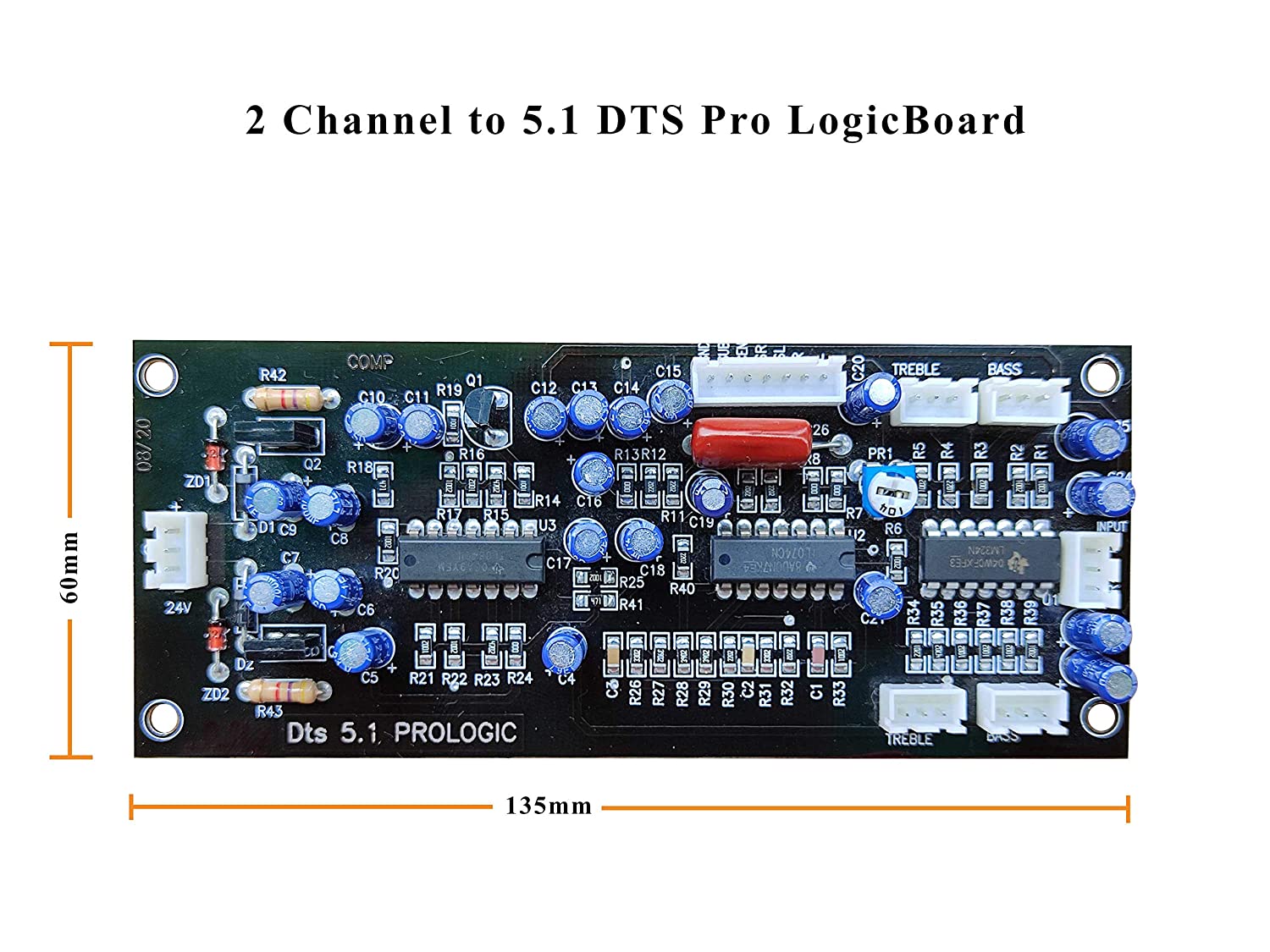
Sakthi 5.1 Prologic Board 24V Dual Supply, Development Boards, Single Board Compputers

Prologic Board Circuit Diagram 5 1 Prologic Board Circuit Diagram Archives Circuits99 It is

5.1 Prologic Board Circuit Diagram Diy 5 1 Prologic Decoder Board For Audio Amplifier With

5.1 Prologic Board Circuit Diagram Pcb Layout Audio Surround Pcb Circuits / Circuit diagram is

Salcon Electronics HiFi 5.1 Prologic Decoder PreAmp Amazon.in Electronics

5.1 Prologic Circuit Diagram Hooking Up Home Theatre Technical Article If you are new to

5.1 Prologic Board Circuit Diagram 820 2879 no backlight, BKL_EN resistors messed up. macbook

5.1 Prologic Board Circuit Diagram Pcb Layout Audio Surround Pcb Circuits / Circuit diagram is

5.1 Prologic Circuit Diagram Results Page 4 About 5 1 Decoder Searching Circuits At Next Gr

5.1 Prologic Board Circuit Diagram Pcb Layout Audio Surround Pcb Circuits / Circuit diagram is

Electro India YouTube (EIYT) 5.1 Prologic Decoder Board for Audio Amplifier wit... Audio
5.1 Prologic Board Circuit Diagram Diy 5 1 Prologic Decoder Board For Audio Amplifier With

5.1 Prologic Board Circuit Diagram Diy 5 1 Prologic Decoder Board For Audio Amplifier With

Prologic Board Circuit Diagram 5 1 Prologic Board Circuit Diagram Archives Circuits99 It is